With the circuit, switched 12v+ what it is? The black/green wire which gives volts when the key is on?
That is any source of 12 volts that is switched through the ignition key, so that there will not be a drain on the battery when the bike is off. No, not the Black/Green wire. That's your circuit output. You want to use a Green/Black wire, like on Pin 6.
And after the relay 3, leg 87 i have to put a wire + earth to the diode, and the output of the diode to the koso wire? Or i'm wrong?
Wrong, if I'm reading your description correctly.
First, some reference terms:
* The cathode of the diode is the wire closest to the band marking on the body of the diode
* The anode is the other end, farthest from the band.
1. You want to take the output on Pin 87 of the 3rd relay and wire it to the Anode of your 12V LED that you will use for the Neutral indicator. The Cathode of the LED will go to ground.
WARNING!!! If you plan on using the indicator in the Koso gauge, that light is active low, meaning you must ground the Koso's wire to light the LED. This means you'll need the 4th relay to invert the signal to the Neutral wire. The circuit is below:
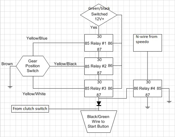
2. You want to solder the Anode of a diode to Pin 87 and solder the Green/Black wire to the Cathode of the diode.
Which diodes and relays I have to buy, is there any reference?
You can use any small power diode, like a 1N4001, iN4004, or similar.
You can use any relay that (1) has a 12V DC coil and (2) has contacts rated for 1 Amp or greater. The one you select will be based on availability, cost, size, and other factors. If there is a RS Components store in Spain, check that store for small relays. If you are handy with a soldering iron, you can end up building a very small circuit but probably standard automotive relays will be more readily available to you and easier to wire up given their large size, and clear pin markings.


