Author Topic: Another neutral switch bypass question  (Read 18505 times)

Offline klhoskins

  • Motobrick Curious
  • Posts: 49
Another neutral switch bypass question
« on: September 12, 2015, 08:11:19 PM »
Hey All, wiring up the K75 cafe bike this weekend and was putting together the neutral relay circuit. I decided to go the micro relay route but am completely electronics illiterate. Anyway I was hoping one of you electronics gurus could help me  correlate the micro relay pin-outs to the relay pinouts on the circuit diagram posted on this site.

Take a look and any help would be greatly appreciated.
  • Oceanside CA
  • '90 K75

Offline klhoskins

  • Motobrick Curious
  • Posts: 49
Re: Another neutral switch bypass question
« Reply #1 on: September 12, 2015, 10:27:06 PM »
Scratch the question guys. A few Google searches and some trial and error with a meter got me sorted out. Gonna wire up the circuit and the Acewell tomorrow so hopefully she will be ready to ride!
  • Oceanside CA
  • '90 K75

Offline klhoskins

  • Motobrick Curious
  • Posts: 49
Re: Another neutral switch bypass question
« Reply #2 on: September 13, 2015, 01:33:30 PM »
Turns out I may not have everything right. I've tested the circuit with a 9V battery and it seems to work. When I put 9V to 30/86 on relay one and ground 85 on all three I get 9V on 87 for relay 3. Disconnect ground from 85 on either relay and I get no output. This is correct right?

On the  bike I've connected as follows but do not get 12v out when in neutral and/or clutch pulled. Any troubleshooting ideas?

* green/black to relay 1 30 and all relays 86
* yellow/blue to relay 1 85
* yellow/black to relay 2 85
* yellow/white to relay 3 85
* black/green to relay 3 87
  • Oceanside CA
  • '90 K75

Offline rbm

  • ^ Quintessential Motobricker
  • Posts: 2308
Re: Another neutral switch bypass question
« Reply #3 on: September 13, 2015, 10:11:16 PM »
The four relay circuit should work in the following way.


Bike in Gear
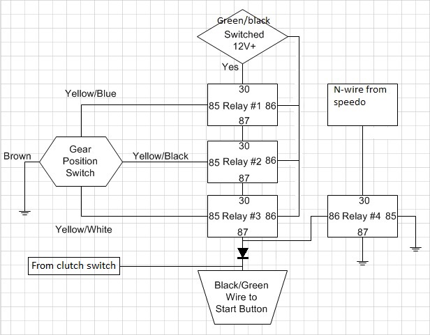
If any gear is selected on the transmission, the TGPI switch will have one or more wires open circuit.  In this state, one or more relays 1, 2 or 3 will not be engaged.  Therefore the output on relay #3 to the Black/Green wire will be off and the start circuit will not work.  At the same time, Relay #4 receive no power on its coil and it is disengaged as well.  The Neutral light is open circuit in this state; no current can flow through Relay #4 contact to ground.  The Neutral light should be off.


Bike in Neutral
When the bike is in neutral, all three wires from the TGPI switch are grounded; relays 1, 2 and 3 are all engaged and +12V is delivered to Black/Green wire and Relay 4's coil.  The bike can start without the clutch pulled in because +12V is now applied to the start circuit.  Relay 4 is engaged because power is applied to its coil.  Current can now flow through Relay 4's contacts to ground and the Neutral light will turn on.

This circuit ASSUMES the neutral light in the speedo is an LED and had one side connected internally to +12V.  If this is not the case with your speedometer, you will have to tell us what the manufacturer expects for the installation.

Turns out I may not have everything right. I've tested the circuit with a 9V battery and it seems to work. When I put 9V to 30/86 on relay one and ground 85 on all three I get 9V on 87 for relay 3. Disconnect ground from 85 on either relay and I get no output. This is correct right?
That seems to be correct based on your description.

* green/black to relay 1 30 and all relays 86
* yellow/blue to relay 1 85
* yellow/black to relay 2 85
* yellow/white to relay 3 85
* black/green to relay 3 87
Your wiring list is correct for a 3-relay circuit.  The fourth relay and the diode are required if you want a neutral light.

If you'e not getting +12V at the start switch with the clutch pulled, then you may have a defective fuse #1.  Maybe your kill switch is engaged?
  • Regards, Robert
Toronto, Ontario

1987 K75 - Build Blog @http://k75retro.blogspot.ca/

Offline klhoskins

  • Motobrick Curious
  • Posts: 49
Re: Another neutral switch bypass question
« Reply #4 on: September 13, 2015, 10:35:33 PM »
Thanks for the info RBM. New to the bike so do you have any tips for testing the TGPI switch? Is it just a matter of putting a meter with - to any ground and + on each of the three wires and testing resistance when in neutral?

I'm fairly certain the circuit is working because when I run all three wires from 85 straight to ground the bike starts. When I pull any one of the three 85 wires from ground the bike doesn't start.

I've tested all of the fuses so no issue there and the bike started fine before pulling the gauge cluster.
  • Oceanside CA
  • '90 K75

Offline rbm

  • ^ Quintessential Motobricker
  • Posts: 2308
Re: Another neutral switch bypass question
« Reply #5 on: September 13, 2015, 10:41:28 PM »
This IBMWR article will help you to test the TGPI.

If your bike won't crank with the clutch pulled in in any gear, then there's something up.  The way power is delivered to the start button is like a logical OR circuit -- either the clutch pulled in OR the gearbox in neutral OR both should allow the bike to crank over.  You hinted NEITHER option worked on yours.
  • Regards, Robert
Toronto, Ontario

1987 K75 - Build Blog @http://k75retro.blogspot.ca/

Offline klhoskins

  • Motobrick Curious
  • Posts: 49
Re: Another neutral switch bypass question
« Reply #6 on: September 13, 2015, 10:53:23 PM »
Bottom line on the entire circuit is that it simply delivers 12v from green/black to black/green correct? where is that 'Or' decision made and which wire delivers that signal when the clutch is pulled?

I'm going to apologize in advance if these are stupid question but as stated, I know nothing about wiring.

Thanks!
  • Oceanside CA
  • '90 K75

Offline rbm

  • ^ Quintessential Motobricker
  • Posts: 2308
Re: Another neutral switch bypass question
« Reply #7 on: September 13, 2015, 11:07:00 PM »
Bottom line on the entire circuit is that it simply delivers 12v from green/black to black/green correct? where is that 'Or' decision made and which wire delivers that signal when the clutch is pulled?

I'm going to apologize in advance if these are stupid question but as stated, I know nothing about wiring.

Thanks!
If you examine the wiring diagram for the bike, you'll notice that the Green/black wire from the diode of neutral detect circuit and the green/black wire from the clutch switch are joined together right at the start button.  This forms the electrical equivalent of an "OR" function.  +12V could be delivered to the start button on either of the wires or both of the wires at the same time -- it doesn't matter.  So long at +12V is present on one side of the start button.

The diode is an important element in the design;it isolates the two circuits from each other.  Have you included it?

Have you sized the micro-relay's switch contacts to make sure they handle 450mA minimum?  That will be the current drawn by the starter relay, so your relays have to safely pass that current.
  • Regards, Robert
Toronto, Ontario

1987 K75 - Build Blog @http://k75retro.blogspot.ca/

Offline klhoskins

  • Motobrick Curious
  • Posts: 49
Re: Another neutral switch bypass question
« Reply #8 on: September 14, 2015, 10:58:42 PM »
Hey RBM, the micro relay I used is a HK19f. The specs are below and as stated, everything worked flawlessly prior to removing the gauge cluster so I don't think there is an issue with the TGPI or clutch switch. However it does seem as if the TGPI isn't grounding the relays but I'm not sure how to test that. I also have no answer as to why it doesn't start with the clutch pulled :dunno2:

Product Name : PCB Power Relay;Model : HK19F
Coil Voltage : DC 12V;Contact Capacity : 1A 125V AC,2A 30V DC
  • Oceanside CA
  • '90 K75

Offline rbm

  • ^ Quintessential Motobricker
  • Posts: 2308
Re: Another neutral switch bypass question
« Reply #9 on: September 15, 2015, 07:40:37 AM »
The relay contact ratings are sufficient.

To test the TGPI, test for continuity between each of the three Yellow/XXXX wires and the Brown wire from the plug end of the switch (disconnect from the harness).  The TGPI switch indicates the gear by grounding each of the three wires in a pattern that creates a binary number between 0 and 7.  The Yellow / White wire from the TGPI switch is the least significant bit (LSB) and the Yellow / Blue wire is the most significant bit (MSB).  In some gear positions, the circuit will be open.  In other positions, the circuit will be closed.  If you get continuity, then the switch is working.

Go back to basics.  Disconnect your relay circuit and debug the clutch circuit.  With the clutch pulled, test for +12V on the start button wire at the right hand switch cluster connector under the tank , and for 0V when it is not pulled.  Get that circuit working right, then introduce your relay circuit.  You'll have a very difficult time of it if you are trying to troubleshoot 2 or more problems at the same time.
  • Regards, Robert
Toronto, Ontario

1987 K75 - Build Blog @http://k75retro.blogspot.ca/

Offline klhoskins

  • Motobrick Curious
  • Posts: 49
Re: Another neutral switch bypass question
« Reply #10 on: September 16, 2015, 08:17:26 PM »
So when doing a continuity test between the ground wire and any of the yellow wires in picture #1, it's open in any gear.

When testing continuity test between the wires in pic2 it's open with or without the clutch pulled. I assume that's the clutch sensor plug.

I'm 100% as I know for a fact the Neutral light worked and the bike would not start in gear before removing the gauge cluster. Which wire is the start button wire. 
  • Oceanside CA
  • '90 K75

Offline rbm

  • ^ Quintessential Motobricker
  • Posts: 2308
Re: Another neutral switch bypass question
« Reply #11 on: September 16, 2015, 08:56:39 PM »
The Brown wire on the male plug is the common wire which is connected to the moving wiper on the switch; all the yellow/xxx wires are individual outputs which get connected with the common wire in some combination based on the currently selected gear.

The TGPI outputs a binary number by connecting one or more Yellow/xxxx wires to the common, using the following truth table:


I hope you were not taking your continuity tester and placing one lead on the frame and testing with the other lead.  You'll need to place one lead on the pin connected to the Brown wire (Pin 31 in the diagram above) and the other lead to one of the Yellow/xxx wires currently under test (Pins A, B or C in the diagram above).

Yes, the photo shows the connector for the clutch switch.  Make sure you physically trace the cable with the yellow wires back to the switch on the clutch handle.  It's not uncommon to mix up connectors and plug the choke switch into the wrong connector.  Both the choke switch and the clutch switch are exactly the same and both of their respective connectors are on the left side under the tank. It's a very easy and embarrassing mistake to make.

You will find the Black/Green for the start button on Pin 6 of the 9-pin connector on the right side under the tank (the connector covered with a clear plastic protector).  You will be looking for +12V on that wire when (1) the ignition is on AND (2) the kill switch is in the normal position AND (3) the clutch is pulled in.
  • Regards, Robert
Toronto, Ontario

1987 K75 - Build Blog @http://k75retro.blogspot.ca/

Offline klhoskins

  • Motobrick Curious
  • Posts: 49
Re: Another neutral switch bypass question
« Reply #12 on: September 16, 2015, 09:33:18 PM »
Much thanks for the quick and comprehensive info. This gives me a few things to look at. I was using the brown male pin when testing so I'm not sure what's going on there.
  • Oceanside CA
  • '90 K75

Offline klhoskins

  • Motobrick Curious
  • Posts: 49
Re: Another neutral switch bypass question
« Reply #13 on: September 16, 2015, 09:52:59 PM »
One other stupid question just to make sure I'm not missing anything.

The bike being on the side or center stand has no effect on what we are discussing right?
  • Oceanside CA
  • '90 K75

Offline rbm

  • ^ Quintessential Motobricker
  • Posts: 2308
Re: Another neutral switch bypass question
« Reply #14 on: September 16, 2015, 10:01:58 PM »
K75's don't have a side stand switch.  Those are on late model K100-16V and K1100, to my knowledge.
  • Regards, Robert
Toronto, Ontario

1987 K75 - Build Blog @http://k75retro.blogspot.ca/

Offline klhoskins

  • Motobrick Curious
  • Posts: 49
Re: Another neutral switch bypass question
« Reply #15 on: September 17, 2015, 09:11:36 PM »
Spent another hour on it and made no progress. I don't see any wiring other than the horn/signal switch coming from the clutch assembly other than the choke sensor cables. I also get no continuity on the TGPI sensor so??? Ended up bypassing it so at least I can start it.

Just to confirm a couple things on the Acewell... As of now all I have is RPM, turn and oil light.

The stock mph sensor will not just plug in and function so it's best to use the sensor that came with the Acewell right? I get no speed reading.

The fuel indicator is showing low even though I have a full tank. I did use the supplied 100ohm resistor. Any fix for that? 
  • Oceanside CA
  • '90 K75

Offline rbm

  • ^ Quintessential Motobricker
  • Posts: 2308
Re: Another neutral switch bypass question
« Reply #16 on: September 17, 2015, 10:00:26 PM »
The stock mph sensor will not just plug in and function so it's best to use the sensor that came with the Acewell right? I get no speed reading.
That's correct.  The stock speed sensor is incompatible with the acewell.

The fuel indicator is showing low even though I have a full tank. I did use the supplied 100ohm resistor. Any fix for that?
What is the Acewell expecting for fuel level input?  What resistance for low fuel?  What resistance for full tank?  If it expects Japanese style input, the BMW is opposite.  You have to flip the resistor board in the fuel sender.  See my writeup on the K100-forum.
  • Regards, Robert
Toronto, Ontario

1987 K75 - Build Blog @http://k75retro.blogspot.ca/

Offline alex.tnt

  • Curious
  • Posts: 2
Re: Another neutral switch bypass question
« Reply #17 on: October 06, 2017, 03:14:25 PM »

I have solution at neutral problem.
This small central unit allows neutral light without counts miles.
Price 35 euro + sp
If you are interest contact me at alex.tnt@aruba.it
  • Italy
  • k75

Offline Panchoplanet

  • Motobrick Curious
  • Posts: 44
  • Trying to keep it logical.
Re: Another neutral switch bypass question
« Reply #18 on: October 14, 2017, 10:28:28 PM »
Is this similar to the relay from Unit garage?


Can you explain or show schematic on how it works?


Thanks,  Pp.
  • Red Hook, NY
  • 1991 K75s

Offline alex.tnt

  • Curious
  • Posts: 2
Re: Another neutral switch bypass question
« Reply #19 on: October 15, 2017, 10:03:59 AM »

yes it is similar at relay module, but this is very small,
because i have used electronics components, not relay.
thanks
  • Italy
  • k75

Offline Panchoplanet

  • Motobrick Curious
  • Posts: 44
  • Trying to keep it logical.
Re: Another neutral switch bypass question
« Reply #20 on: October 15, 2017, 10:43:12 AM »
Thanks for replying to my question, will get back to you.
Considering other alternate setup with RBM, his unit allows the use of BMW's factory speed sensor allowing me to eliminate the Koso speedo pick-up.
Plus also considering replacing Koso with aftermarket speedo and tach gauges with analog functions instead of digital.


Will keep you posted.


Pp.
  • Red Hook, NY
  • 1991 K75s

Tags: