You can stub off the following wires comming from the ecu connector using a motogadget:
- Green/yellow (sidestand)
- Brown/black, grounding connector for a relay,
- Brown/blue, grounding connector for a relay,
- Blue/Black, (dont remember its original use, dont confuse it with black/blue RPM)
Green black should run to ignition.
Clutch is yellow black.
M-unit outputs shouldnt have to be connected to a fuse because the m-unit has a failover.
The startup of the fan is a combination of draw, especialy when using a relay, the sensor has currency which starts to send signal when reaching 90celcius
Opening the relay which then starts to draw for input to the fan, the startup of the fan can draw up to 24volts -iirc-, dont pin me down on this.
all the while you have connected it to a 12v output.
Anyway, here is your diagram modded for m-unit use.
and my m-unit wiring diagram with all optional routes for connecting to the m-unit.
[ Invalid Attachment ]
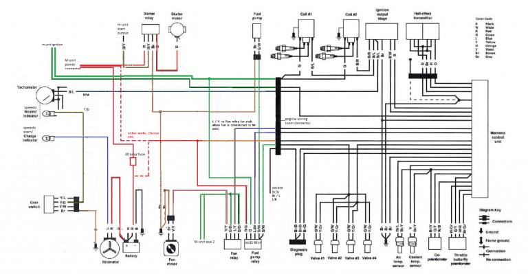
 SwapWiringDiagram.png (49.26 kB . 768x399 - viewed 488 times)
side note. The wiring diagram is the one I currently use facing no issues on power draw. BUT it's designed to run a 2valve bike on 4valve electronics.


