#1 Brown Wire/
White Stripe = 4L fuel indicator input to Pin 7 on OEM gauge
#2 Brown Wire/ Black Stripe = 7L fuel indicator input to Pin 8 on OEM gauge
#3 Green Wire/
White Stripe = Power to fuel pump
#4 Brown Wire = Ground
The replacement pin connector looks to be the Optional Alarm Connector out of the relay box. Someone clipped it off to replace the original connector that probably wore out. Anyway, to figure out the wiring is straight forward.
1. Empty the tank of gas. You will now use an ohm meter set to resistance to test the 4 pins on the tank.
2. Clip a wire with alligator clips on its ends, one end to the pump positive terminal and the other end to the black lead on the ohmmeter..
3. Pick a pin and start testing the resistance with the red lead of the ohmmeter. You're looking for a pin with 0 ohms. Three of the pins will read around 600-800 Ohms but only one will read 0.
Once found, you've identified the pump power pin, mark it.
4. Move the alligator clip from the pump positive terminal to the pump negative terminal.
5. Pick a pin from the remaining three and start testing the resistance again. You're looking for a pin with 0 ohms. Again, two of the pins will read around 600-800 Ohms but only one will read 0. Once found, you've identified the ground pin, mark it.
6. The remaining two pins are the thermistors. I can't tell you how to find the 7L sensor or 4L sensor between the other pins but you'll find out once you test.
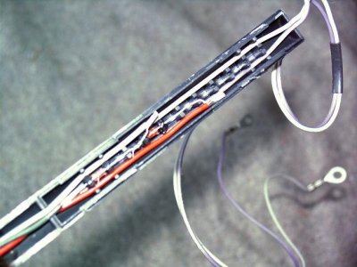
FYI, the inside of the fuel level sender looks like this: