Author Topic: Observe caution when replacing the Starter Relay with an aftermarket one  (Read 3347 times)

Offline rbm

  • ^ Quintessential Motobricker
  • Posts: 2308
It's a common complaint - a low battery voltage can cause the starter relay to fail resulting in the starter motor failing to shut off even after turning off the ignition.


So, some people fix the problem by buying an aftermarket starter relay and replacing the OEM one.  It's a cheaper option however  BE CAREFUL TO SELECT A RELAY THAT HAS PROTECTION DIODE ACROSS THE RELAY COIL.  Yes, all caps.  If you fail to observe this caution, you risk very quickly taking out your Ignition Control UNIT (ICU) which is a very expensive mistake.


There was a discussion about this topic on EEVBlog, but I'll include the two oscilloscope traces from that thread to illustrate the threat.  When the engine catches, the ICU cuts the connection to the relay.  The electricity does not stop flowing through the relay coil immediately and a very large voltage spike can result.


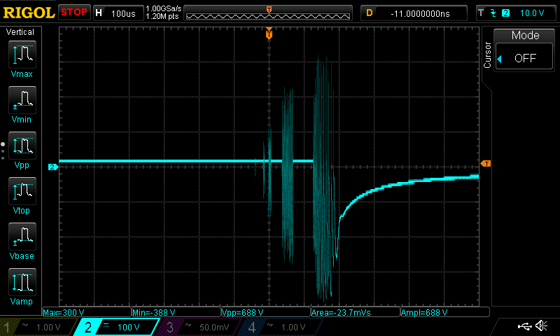
The oscillation apparent on this scope trace shows the voltage spike when power is removed from an automotive starter relay.  Take note of the annotation at the bottom.  The minimum observed +ve voltage is 300V, the minimum observed -ve voltage is 388V, the peak-to-peak voltage is 688 Volts.  This same voltage will appear across the transistor driver in the ICU, which will immediately kill the device.


This whole threat can be eliminated by including a simple 1N4007 diode across the starter relay coil in the reverse direction, as shown below


The trace below shows the same relay with a snubber diode installed as above.


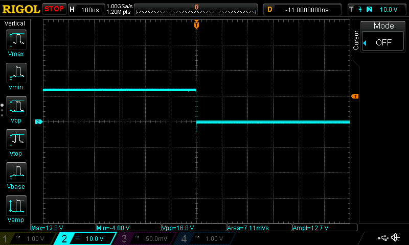
Now note that the oscillations are completely damped and the peak-to-peak observed voltage is 16.8 Volts.


If you purchase an aftermarket starter relay, just make sure to add the required diode.  It will cost you $0.50 more but you potentially save having to replace a $200.00+ ICU.
  • Regards, Robert
Toronto, Ontario

1987 K75 - Build Blog @http://k75retro.blogspot.ca/

Offline tagaz

  • Curious
  • Posts: 6
Robert,


Thank you for the word of caution.


I am not sure I understand the mod correctly.


I see, in the schematic you proved for the mod, a common diode symbol and the other is maybe a Zener diode
or a Tunnel diode.


Would it be possible for you to clarify, in the most simple of terms exactly how to execute the adding of the diode.
I am experienced working with electronics. But I am not experience working on Brick Bikes.
If you would provide an image of how the mod/addition of the diode looks like, I would be most appreciative.
Then I will save it to my library of files for future reference.


Hope never to need this information.
But having the information and not needing it is better than needing it and not having it.


TIA,


Troy
  • Kingman, AZ USA
  • 1985 K 100 RT

Offline rbm

  • ^ Quintessential Motobricker
  • Posts: 2308

I'll see if I can find a picture for you. 


There's no harm using the Zener and adding the Zener will assist the relay in releasing faster.  The zener voltage should be low enough to avoid damaging the ICU's driver, but high enough to prevent the relay holding on too long -- probably 10-15V.
  • Regards, Robert
Toronto, Ontario

1987 K75 - Build Blog @http://k75retro.blogspot.ca/

Offline know_fear

  • Motobrick Curious
  • Posts: 31
Here are some photos of my beejesus starter contactor with diode that I've been running for years now.
The diode is connected in parallel with the coil of the contactor with the line end of the diode towards the positive.


When the start button is pressed to energize the contactor without a diode, a magnetic field builds up around it's coil and stays there as long as the button is depressed. When the button is released and the contactor is de-energized the magnetic field collapses. The magnetic flux collapses through the copper windings in the contactor and generates an electric current in those windings. But wait....the circuit that initially energized the coil is now open, no current can flow. The collapsing field causes the voltage to increase trying to find a path for that current. The diode is required to provide that path.
A diode in that application is sometimes called a flyback or free wheeling diode.


In the photos the red heat shrink is at the end of the diode that is connected towards the positive.
  • BC Canada
  • '85 K100RS, '69 Norton Commando
Know fear,have kids.

Tags: